
With all the cleaning completed as described in our last blog, we could start rebuilding our boat engine. We’d purchased an engine overhaul kit that contained new bearings, pistons and all the gaskets that we would need to hopefully get the engine running again. Could we get it all back together ourselves? On the plus side, we’re both technically minded and we had a good support network. On the down side we had limited parts and tool availability, plus we were working in a borrowed space, not set up for what we needed to do.
Warning – this post contains subjects that may be of a technical/not very exciting nature! But I’ve tried to condense things and focus on the drama and emotion of what went right or wrong. The work took place over many hours and I could probably have written a whole blog on each section.
The Crankshaft Bearings
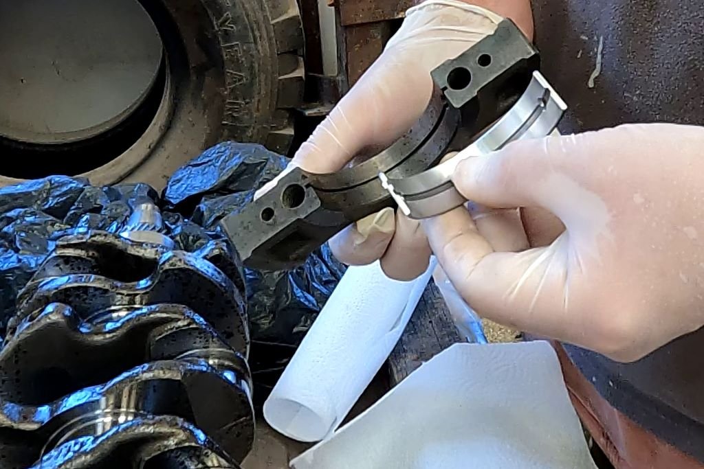
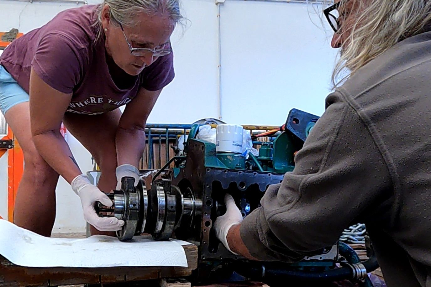
The rebuild began from the bottom up, which meant first refitting the crankshaft. But before it could go back in we needed to replace all of the crankshaft’s bearings. The old ones were coated in rust and strong suspects in the source of the awful squeaking noise when we’d tried to turn the engine over. The overhaul kit contained a full set of bearings and fitting them was fairly straightforward. With the crankshaft resting on a bench, we had easy access. Each half of the curved bearing neatly slotted into machined grooves on the bearing carriers to hold it in place. We then set each half of the bearing carriers around their location on the crankshaft, before torquing the holding bolts. It was extremely important to replace the carriers in their correct order.

What is a Bearing?
A bearing is a smooth piece of metal that acts as a sacrificial interface between other moving metal surfaces. The bearing metal is softer than the crankshaft metal so that it wears first. It is much easier to replace small, worn out pieces of metal than large lumps of metal.
The bearings need lubricant to ensure they don’t run dry because running dry can destroy them. Under normal use, engine oil is thrown around the inside of the crankcase which keeps the bearings lubricated. At that point we had no idea how long it would be before we could run the engine and get oil to where it needs to go. We could have brushed engine oil onto the bearings, but it would most likely have flowed away before we could run the engine. This would risk a dry start – metal on metal without any lubricant could damage and destroy the new bearings.
So, we used a product called Lucas Assembly Lube to aid fitting them. The lube remains sticky until it gets hot, which will happen on first use of the engine. At that point it becomes viscous and runs away into the engine oil. Plus it was green coloured, perfect for an Emerald boat.
The Front Crankshaft Bearing Was a B*****d to Fit
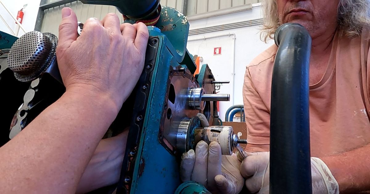
The most difficult bearing to replace was the one into which the front of the crankshaft fits at the front of the engine body. The bearing is a continuous circle, rather than two halves that slot together. It is made to be an extremely tight fit. We had had to hammer the old one out, whilst being extremely careful not to damage any of the other metal faces. It had been slow and stressful work.
A typical workshop has a bearing press for fitting new bearings of this type, but one wasn’t available to us. So, a friend’s suggestion led us to build our own press out of bits from our box of “random things that might come in useful one day”. Amazingly it worked.
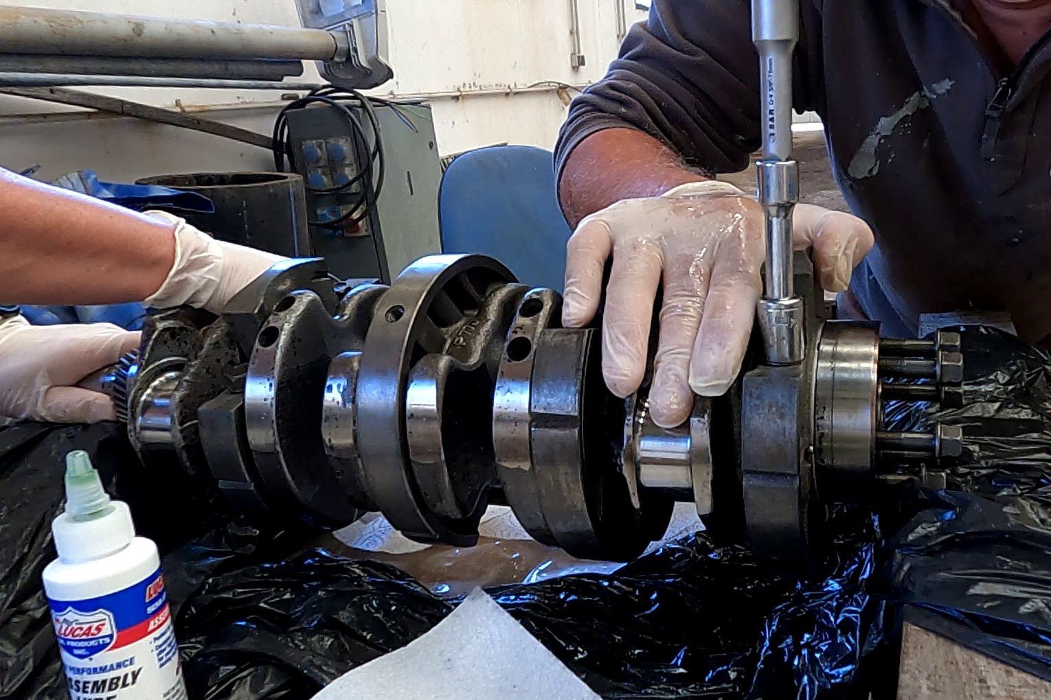
Refitting the Crankshaft
With all the bearings replaced and lubricated, the crankshaft was ready to go back in. We’d already experienced the difficulty of removing it, so we attempted to plan to make refitting it easier. The two biggest issues were firstly the weight and second, access for our hands to support it as it moves through the crankcase.
To ease the weight issue, we built a wooden platform at the back end of the engine to rest the crankshaft on if we needed to. With the crankshaft now covered in sticky assembly lube, it became a magnet for all the dust floating around the shed. So we thought it was a good idea to lay out some paper towels on the platform to try and stop the crankshaft becoming covered in dirt. This was to come back and bite us on the bum.
The Paper Towel Incident
Between us, we shuffled the crankshaft in by tiny amounts, feeding it through each of the bearing carrier holes. When it reached the front bearing, Colin tapped the back end of the crankshaft with a hammer to push it in to the tight fitting hole. It took quite a lot of tapping resulting only in small forward movements. But with patience, it was fully in place.
This was when Colin spotted a fragment of paper towel sticking out from between the crankshaft and the last hole of the crankcase. We couldn’t see how much of the paper was trapped between the surfaces, but regardless of the amount, leaving it was not an option. But, the bearing fitting was so tight we couldn’t pull the paper out without it tearing. Unfortunately, there was nothing for it but to reverse our work and tap the crankshaft back out. Our biggest worry was causing damage to the front bearing whilst we did this. I can confirm that the inside of the shed was blue that day and a few innocent lumps of wood absorbed some of our annoyance.
Thankfully we successfully retrieved all the paper without causing any damage. We repeated the fitting process, gently tapping the crankshaft back in to the front bearing again. Disaster averted.
An afternoon of tapping and adjusting followed as we ensured the crankshaft was in the correct position for the holding bolts to be fitted. We ended the day by giving the crankshaft a few turns. The movement was smooth with an absence of squeaking. It had been a job that we had been very worried about, so the relief felt over completing it successfully was enormous.
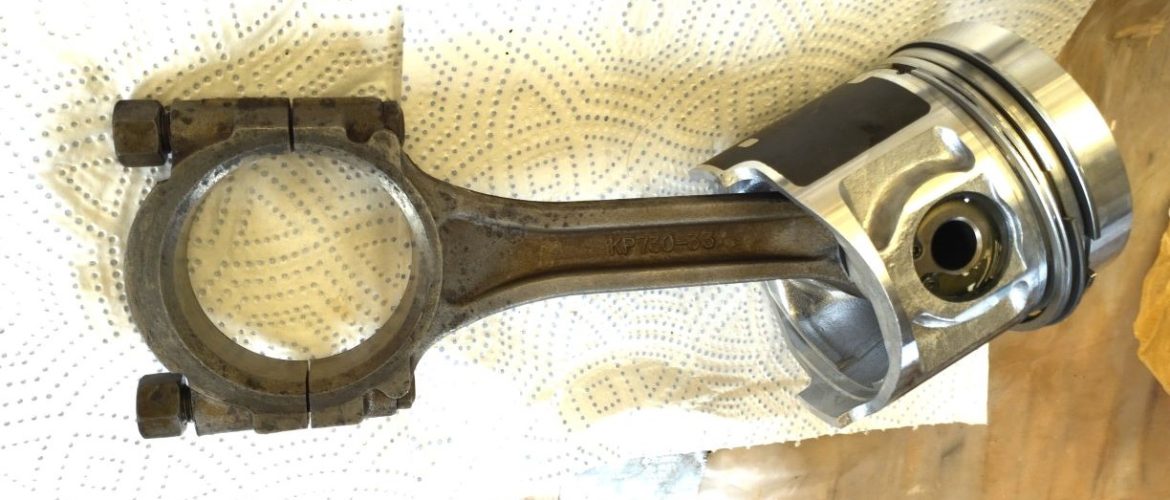
Assembling and Installing the New Pistons
The next job was to construct the new pistons and install them into the cylinders.
The overhaul kit for our engine type included four new pistons. They came constructed but we needed to take the gudgeon pin out in order to attach each piston to its conrod. This involved removing, then refitting, a very fiddly circlip. Circlips are the little feckers of the engineering world. They always give us the worry that they’re going to ping off and never be found again. After a bit of a struggle with the first one, thankfully the work on the others went smoothly. We again used liberal amounts of assembly lube on the piston bearings to prevent them seizing up before use.
The pistons have rings that ensure a good seal with the cylinder wall as they move up and down. But, to get the pistons in to the cylinder, we needed to squeeze the rings in. Once inside, they would expand to the size of the cylinder. However, trying to squeeze the rings by hand whilst slotting the piston in was nigh on impossible. Instead, a €10 tool saved the day. We located the piston into the top of a cylinder, then slid the tool on top. Colin then tightened the tool’s closing nut. This squeezed the rings in for us and the pistons slotted smoothly into the cylinders.
We worked together with Colin at the piston end and myself at the open bottom end of the engine. As Colin slotted a piston in, I guided each conrod into place on the crankshaft. Colin then torqued the conrods in place.

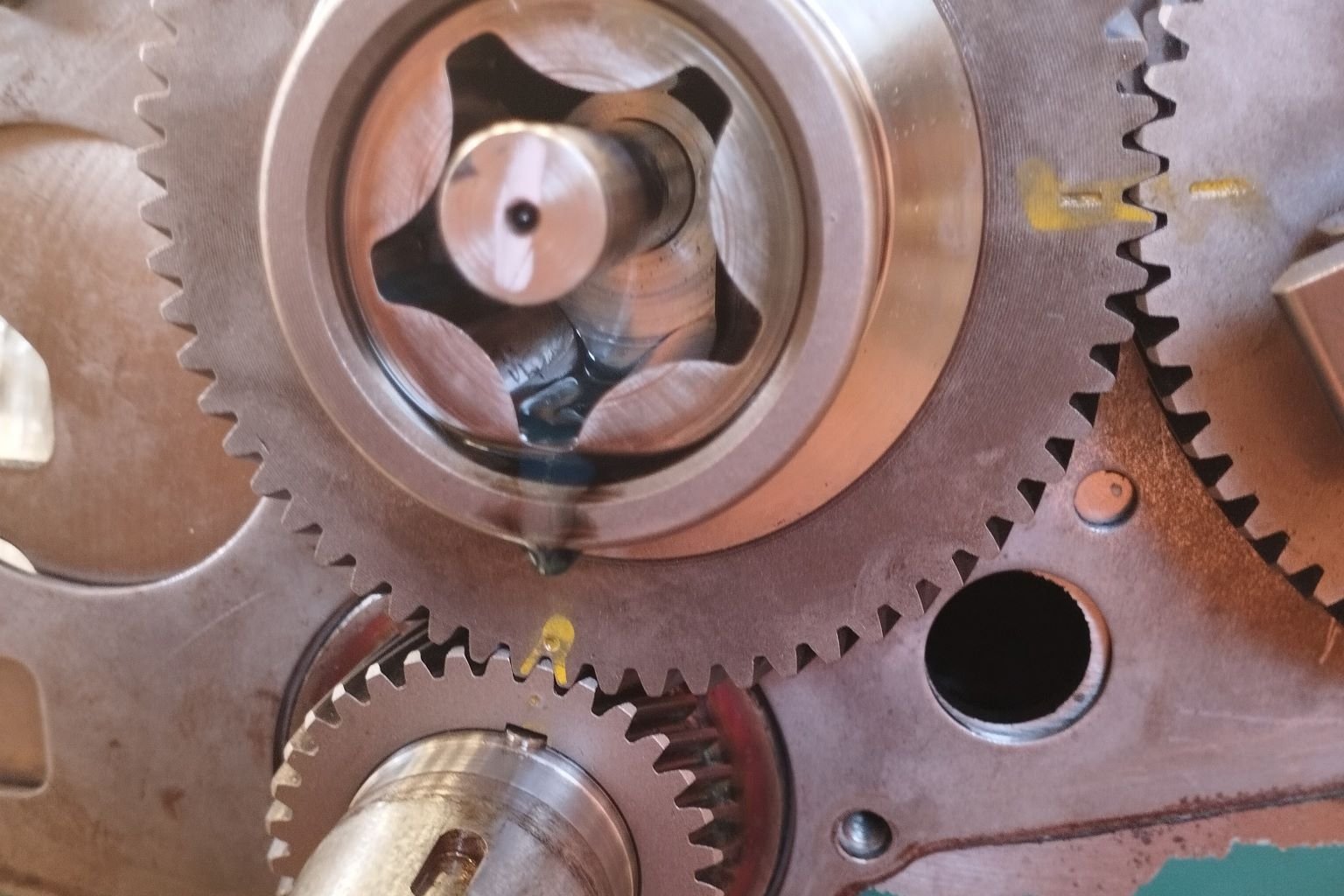
The Timing Gears
With the crankshaft work complete, we moved on to the timing gear on the front end of the engine. The timing gear has three metal cogs, which must be precisely aligned with each other. Failure to align would result in the pistons going up and down out of sync with the valves opening and closing. This would result in the pistons hitting the valves and ultimately a big bang.
There are markings on each of the cogs that help with the alignment. Given that we’d aligned the cogs when we took them off, fitting them was straight forward.
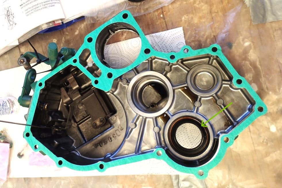
The Timing Case
The timing case is a cast aluminium component that covers the timing gear at the front of the engine. When the engine is running, hot oil sloshes around inside to help the timing gear turn smoothly.
Within the case is a thick rubber oil seal that fits tightly over the front of the crankshaft. We had a new seal in the overhaul kit, so we decided to replace it. But it was a hard job to get the old one out and the new one in.
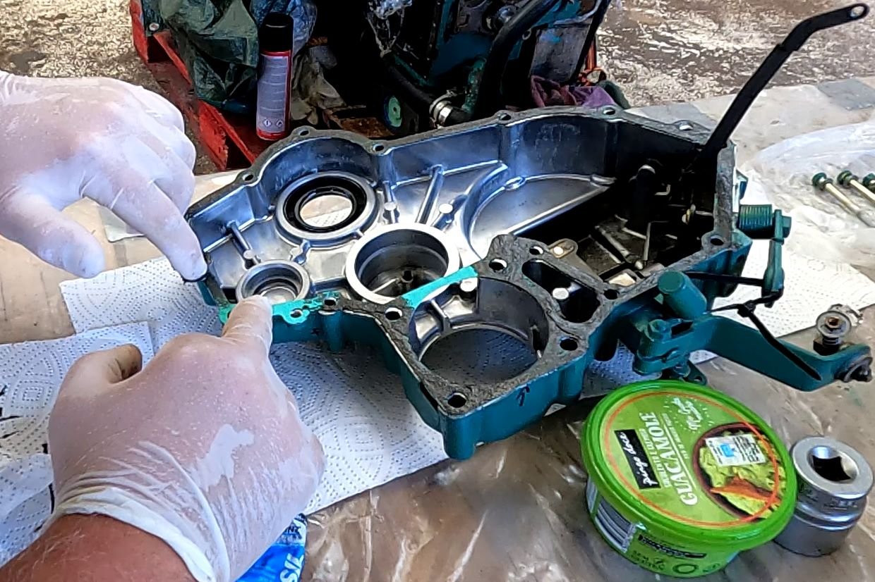
To Gasket Sealant or Not?
Several of the engine parts use a gasket between where there is a metal to metal join. The paper and rubber composite gaskets smooth out any imperfections between the metal surfaces and ensure an oil tight fit. In theory.
The timing case is one such place where a gasket is used to seal the connection between it and the engine body.
We had carefully removed and cleaned away all traces of the old timing case gasket, using copious amounts of brake cleaner. However, aluminium is a soft metal and despite being careful, we could have created imperfections that the new gasket could not fill. To mitigate this, viscous products exist called gasket sealants which work with the gasket to fill in these imperfections. We had received lots of great advice over the course of the engine rebuild. However, nothing divided people more than the question: to gasket sealant or not to gasket sealant? Some said yes, others were an emphatic no. We inadvertently started a forum war.
We decided to go with the yes camp as it felt like doubling down on sealing could only be a good thing. We used a sealant called RTV, which was the only product available on the island. This is a quick setting, thick black goo that we spread on both sides of the gasket surface.
Colin then pressed the timing case in place and torqued up each of the 15 or so bolts.
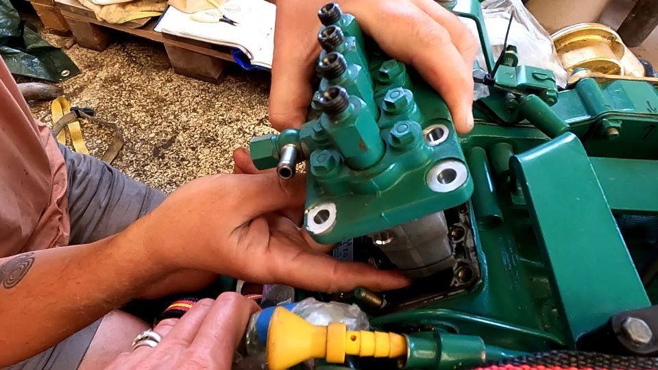
The Injection Pump
The injection pump has its own metal gasket that didn’t need replacing. It was a straightforward job to align it the right way up. However, what was fiddly was to connect the governor to the pump at the same time as fitting the pump. The governor is a spring that controls the speed of the engine. A circlip holds it in place, and as previously mentioned, circlips are feckers. Our worry was that the clip would ping off into the engine. So, to prevent this, we tied a piece of thread around the clip. Then, if it did ping off, it couldn’t go far. It worked a treat, there was no pinging off and once connected, the thread was pulled out of the way.
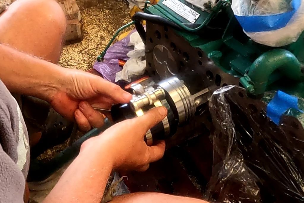
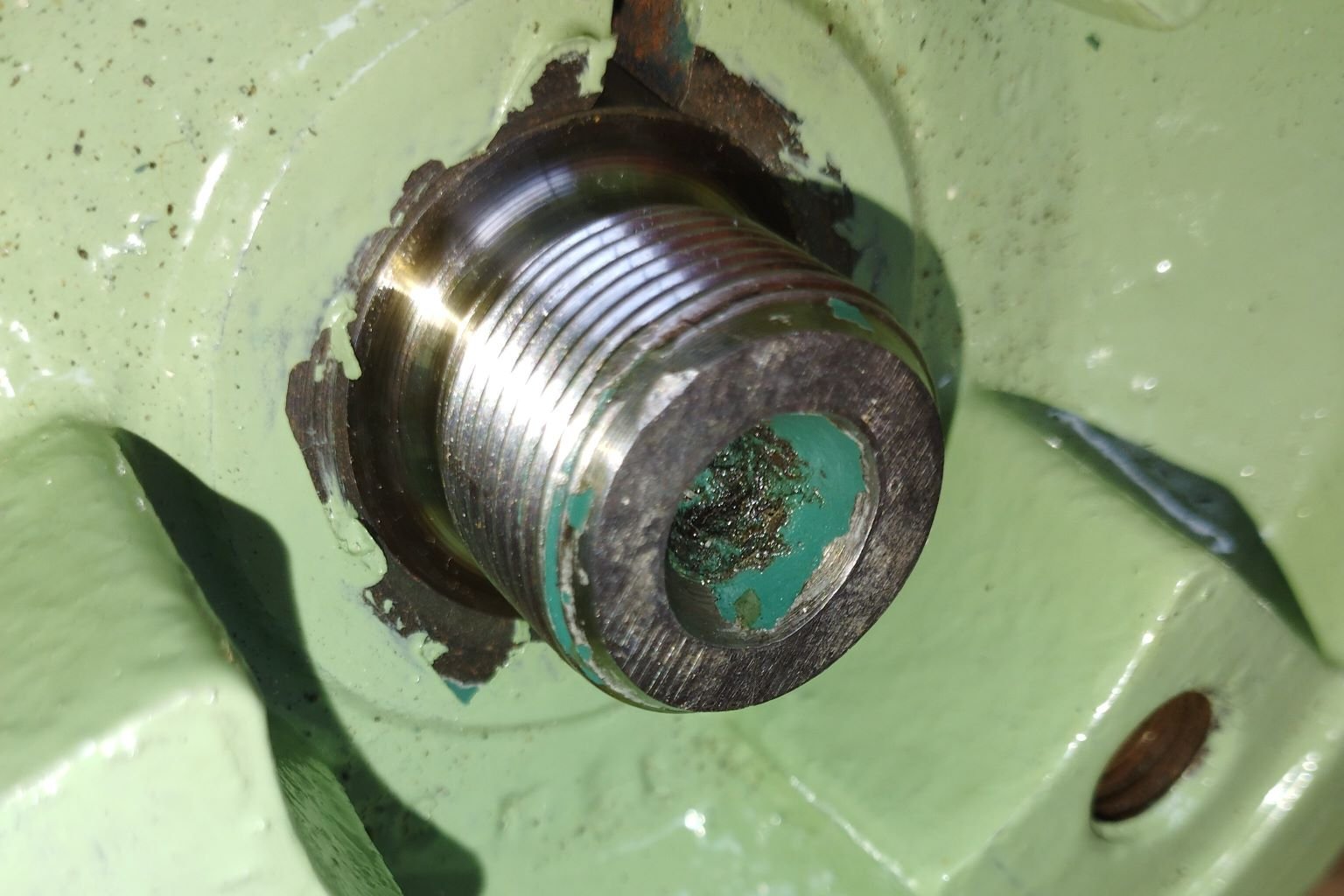
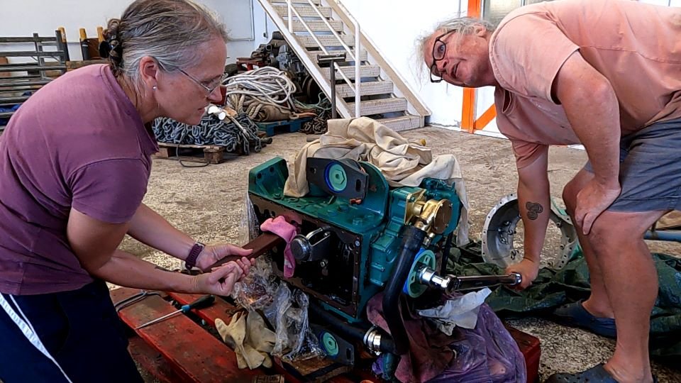
The Crankshaft Pulley Nut
Next was the crankshaft pulley and the nut that holds it in place on the end of the crankshaft. The pulley drives the alternator belt and the fresh water cooling pump. Hence the nut has a lot of pressure against it and it has to be tightened to 300nm. Most of the other engine bolts are torqued to between 10 and 50nm, the head bolts are 90nm.
During the process of removing the pulley, we accidentally damaged some of the threads on the crankshaft. As a result of this, the nut would not go back on. Colin tried to fix it by filing the damage with needle files, but it made things worse. We then received a top tip – use the valve grinding paste! This worked a treat. Colin spread a thin layer of paste on to the threads, and gently worked the nut back and forth. The nut gradually moved further down the threads, until it was fully on. We took it off, cleaned up the paste, fitted the pulley and retightened the nut.
Amongst the many tools we have bought to rebuild the engine, we now own a family of torque wrenches. Now it was time to use the largest wrench to tighten up the nut to 300nm.
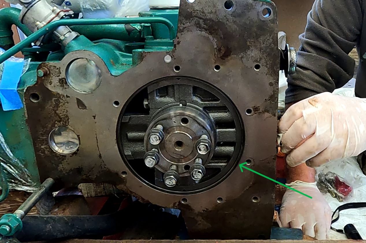
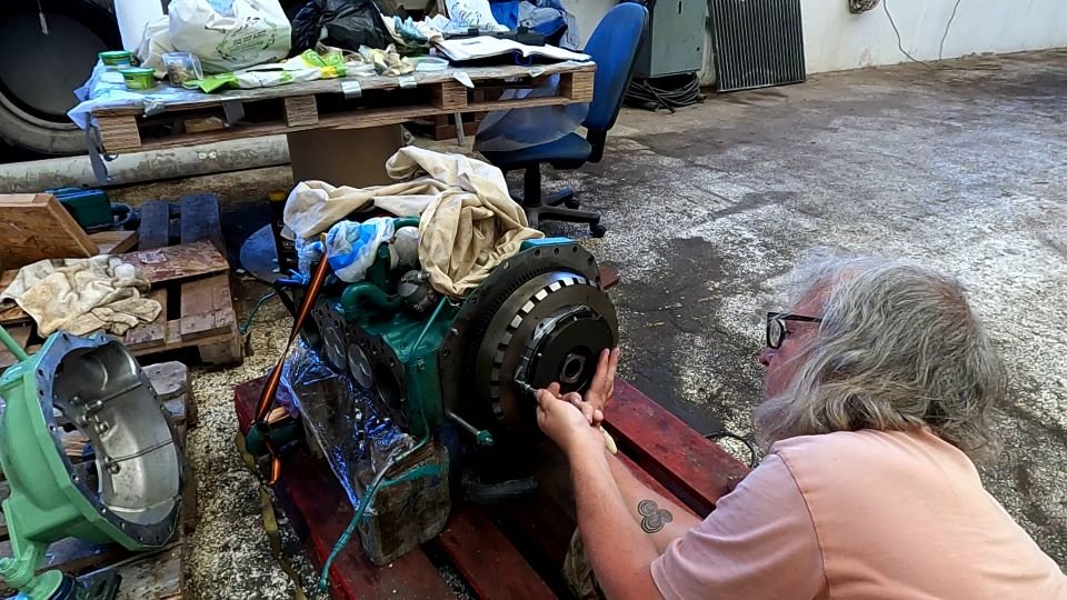
The Back of the Engine
The back of the engine was relatively straight forward and quick to reassemble. First we applied a good coating of high temperature silicon sealant on to the back face of the engine. This was to hold both the rubber oil seal that fits over the back end of the crankshaft and the back plate in place.
We were nervous about this seal and still are. Only time will tell if we used enough sealant to prevent hot oil leaking out.
The flywheel was next, followed by the damper plate and finally the bell housing. The gear box attaches at this point, but we’d found a hole in the gearbox case, which needed repairing. I’ll cover this in a separate blog.
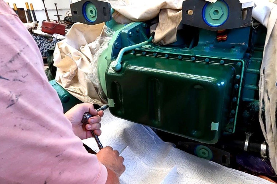
The Oil Sump / Oil Pan
When we took the original oil sump off, we could clearly see that salt water had been inside. The paint at the lowest end of the sump was peeling away and there was a large area of rust. The same company that sold the overhaul kit also had replacement sumps at a not too eye watering price. So we decided it would be worth replacing the old sump with a new one, rather than repairing the old.
We painted the outside of the new sump a complementary green to the engine body to protect it in the engine room. Even if the engine doesn’t work again, it will look like a lovely lump of art.
As this would be our last chance to see inside the crank case, we gave it a good inspection to check for any new rust spots. It looked OK, but for good measure we painted on another protective coating of engine oil.
Like the timing case, the sump also has a gasket between it and the bottom of the engine case. We used the same logic that had led us to apply an additional sealant on the timing case gasket, and applied RTV to both sides of the sump gasket.
Colin had prepared each of the 30 sump bolts with anti-seize paste. This would help them come out easier if we needed to take the sump off again. If only we’d known how prophetic we’d been at that point.
The oil sump was the last component to be fitted before we could turn the engine the right way up. All further work, such as fitting the head, needed the engine to be the right way around. It felt like we’d reached a momentous point in our engine rebuild journey.
The Timing Case Gasket Disaster
Most of the work above took place during late March and April. The yard was closed for some days for Easter and life stuff slowed us down. This meant several weeks had passed between fitting the timing case and turning the engine the right way up. Enough time for some oil to find its way from inside the timing case and through an unspotted tear in the gasket. The tear was on the side of the engine that was currently facing downwards, and not in our line of sight. None of the other engine work had been in this area, so this dribble of oil had gone unnoticed.
Our plan to set the engine upright involved creating a rope harness. It would tie to strong points on the engine, then loop over the tangs on the yard’s forklift truck. We tied the rope onto the engine’s feet, passing it twice under the body of the engine.
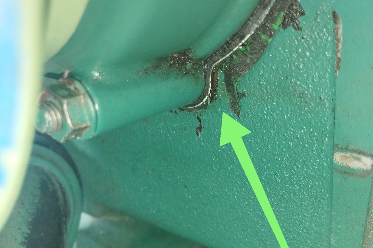
I was double checking Colin’s knots when I saw a small pool of oil under the front of the engine. I almost didn’t mention it. We’d used liberal amounts of oil when rebuilding that end of the engine, so I told myself it could have come from anywhere. But I decided to point it out to Colin, just in case. We traced it upwards to a corner of the timing case, that was facing downwards. We had to take photos as it was difficult to get our heads close enough to see it properly.
But there on the photo we could clearly see a piece of gasket material sticking out. It looked like there was a tear, and next to the tear was a small stream of oil.
Several Weeks of Time Lost
The disappointment was overwhelming. We had to walk away for a while to allow the pain to settle to a level that we could deal with in order to then make rational decisions. We had been so close to turning the engine upright. So close to being able to finish the work on the head and then test run the engine. To fix the issue would involve undoing weeks of work and then redoing that work. First the sump would have to come off. Then the crank pulley and nut and remove the injection pump. Finally the timing case itself, whilst hoping not to damage the front crankshaft oil seal. We would then have to clean the joining surfaces of the timing case and the sump and then put it all back together. The only thing in our favour at this point was that we had a second set of gaskets.
We can’t help thinking that this incident had a strong influence on our decisions further down the line. And some of these decisions did not have a good outcome…
This blog is already more long enough, so I’ll cover what happened next in another.
The Social Media Bit: Want to Follow Us?
Thank you for reading this far, we really appreciate it. If you’ve enjoyed our site or found it useful, please consider a donation via the DONATE button below. We’re grateful for anything you can spare!
If you’d like to follow us on other social media platforms (Facebook, Instagram and YouTube), you can do so by using these links:
Or use the link below to track our voyage on NoForeignLand.com.
And finally, you can sign up to receive email notifications of new blogs using the subscribe box at the bottom of this page.
Thank you from Nichola & Colin
A very detailed and well told story Nic ….however it did not convey the depths of despair and frustration you both endured during the rebuild. having followed the saga from the beginning along with many others, I am over the moon you have got so far…well done to you both…
Pingback: Boat Engine Rebuild - The Gasket Debacle - Yacht Emerald