

This article shares our experiences and tips for servicing a hydraulic autopilot. In our case, the unit is a Simrad HLD2000 MK2LS, also known as a Robertson. The servicing involved replacing the seals in the ram, cleaning the components and replacing the hydraulic oil.
Emerald’s Steering System Explained
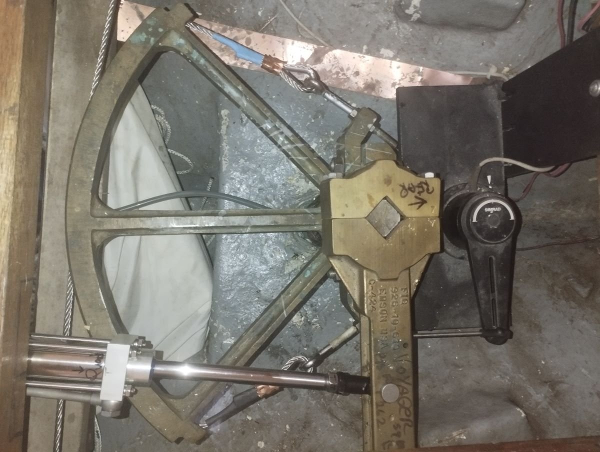
Emerald’s rudder is attached to the boat via the rudder shaft which comes up through the stern of the boat. On top of the rudder shaft is a steering quadrant with the steering cables attached to both sides. As the helm turns, it pulls the cables, which in turn pull the quadrant which turns the rudder. We also have an Edison tiller arm connected to the rudder shaft and to which an hydraulic autopilot ram is attached. The ram is operated by the autopilot.
We have four stand alone methods of steering the boat, which gives us good redundancy if something breaks.
- the helm attached to the rudder shaft via steering cables and a quadrant
- the autopilot attached to the rudder shaft via an Edison tiller and controlled from units in the cockpit and nav station
- an emergency tiller that fits on to the rudder shaft in place of the Edison tiller
- a Hydrovane with its own rudder
Hydraulic Oil Leak From the Autopilot Ram
At the end of a stay in a boatyard, one of the final jobs is to regrease the rudder shaft. The shaft enters the boat’s hull through a hole below the waterline and so is a potential water leak point into the boat. To prevent water ingress, we use wadding stuffed around the shaft which is then packed with grease. The existing grease had dried out during our prolonged stay ashore in warm weather, and hence needed replenishment. Whilst doing this job, Colin noticed a small pool of black liquid on the inside of the hull, below the quadrant. He subsequently traced it back to the autopilot ram.
It seemed to be only a very small leak and this was born out when we checked the oil reservoir level, which looked good. Given that we’d already spent far too long on the hard, we decided to postpone a repair job whilst maintaining a watch for the leak becoming worse. Happily, the autopilot still operated correctly once we were back in the water.
During our 4 day sail to Porto Santo from the Portuguese mainland, we used our Hydrovane steering instead of the autopilot. However, even when the autopilot is not in use, the ram is still attached to the rudder shaft. So, every time the rudder moves, the ram moves. Hence, if we had a failed seal, as was likely, then every rudder movement would only be making the seal’s condition worse. When we next checked the leak, there was a noticeably bigger puddle.
The Simrad HLD2000 MK2LS
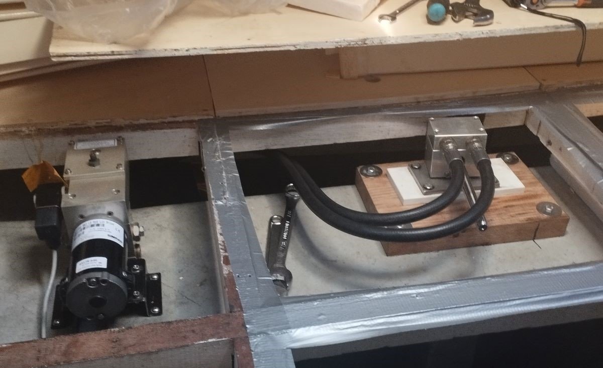
The autopilot that we have is a Simrad HLD2000 MK2LS. Ours is the split version to allow for flexibility over where it is installed in the limited space underneath out bed. It consists of two separate units – a motor and hydraulic pump unit and a hydraulic cylinder unit, also known as a ram. Two hydraulic hoses connect the two units together.
This model is no longer made although second hand units are available – at a cost. Service kits are also no longer available. We could replace it with a newer model, but that’s currently beyond our budget. Until now, the autopilot had worked well for over 20,000nm, and environmentally, we prefer to repair where possible, rather than replace. So we set out to learn the process of servicing a hydraulic autopilot.
Disassembly
Draining the Oil
Before we could move the ram to a better location to disassemble it, we had to drain the system of oil. We did this by removing the hoses one at a time and placing the end into a jug to allow the oil to run out. We then plugged up the hose connection points on each unit.
To drain the oil reservoir, we removed the motor/ pump unit and tipped it up. For the drive unit, we had to work the ram back and forth with it held over a bucket. These methods won’t have removed all of the existing oil, but enough.
Taking the Ram Apart
Unfortunately, we were unable to find any instructions or advice on how to take the ram apart other than someone advising us not to do it ourselves! So, it was going to be a process of studying the parts and using our mechanical skills to carefully make it up as we went along.
Before taking it apart, we marked the assembly with pen to indicate any important positions and in which direction various parts fitted.

Servicing
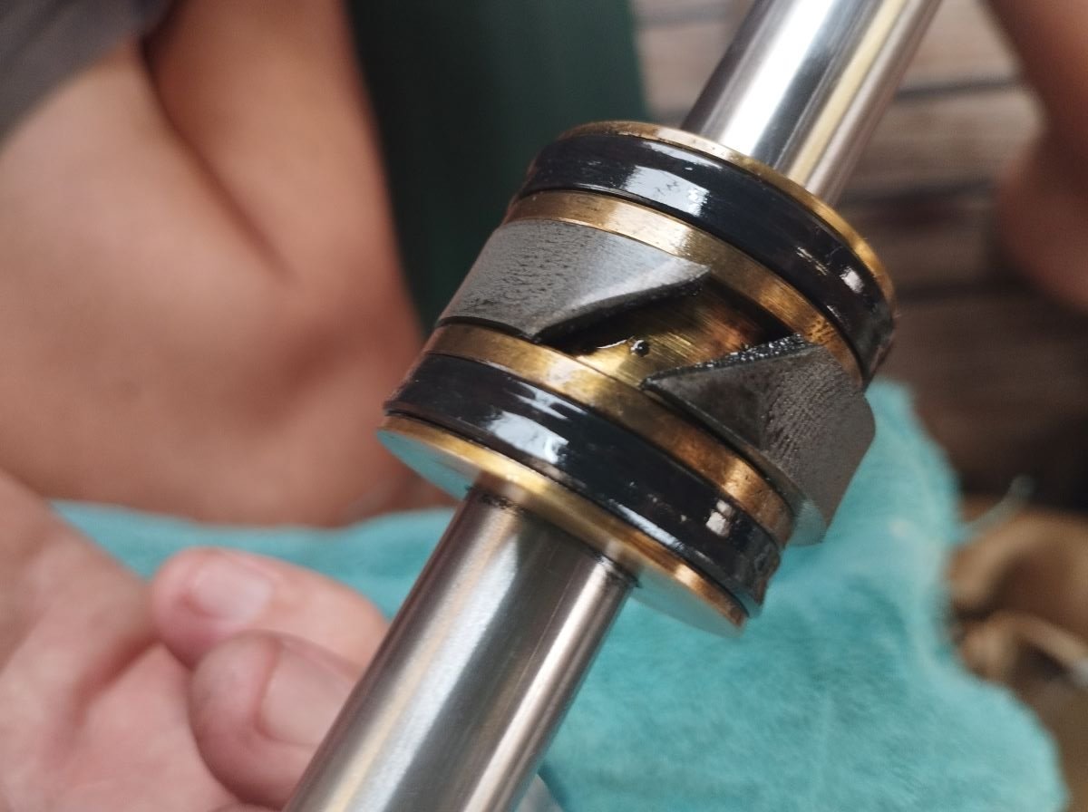
Replacing the Seals
The old seals were removed using needle nose pliers and a small, flat bladed jewellers type screwdriver. We were very careful not to scratch the steel surface of the piston and the aluminium end plates whilst removing the seals.
Fitting the new seals was very fiddly and required a lot of patience to ensure they went on without damage.
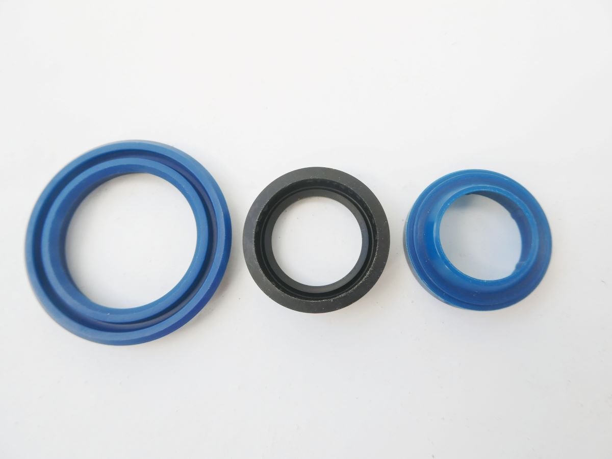
The oil seal has to go into each end piece before the wiper seal, and it is vital to get them the correct way round. The oil seal (the black one in the photo) has a flat face and a face with a groove in it. The flat face lies towards the outside. The wiper seals were relatively easy and just needed some gentle persuasion to pop into their space.
For the seals on the piston (the largest one, called the nut ring) the flat faces lie towards the inner bush. To fit them, one edge was put over the lip and the rest of the seal was gently teased on using a flat bladed screwdriver.

Cleaning the Ram Components
The piston and cylinder are made from stainless steel. We gave them a good wipe and clean using a microfibre cloth and polished the outer cylinder using stainless steel polishing compound.
Cleaning the Breather Valve
There is a valve with a tiny hole in it on top of the oil reservoir. The valve is there to allow any trapped air within the system to escape. However, our valve was completely blocked, meaning air could no longer pass through.
Simrad’s UK support advised us that it’s common for debris to block the breather valve. They suggested to use a 1 to 2mm drill bit to clean it out. With some careful digging using the bit, we were able to dislodge years worth of dust to open the valve up again. We will now endeavor to check and clean the valve on a more regular basis.
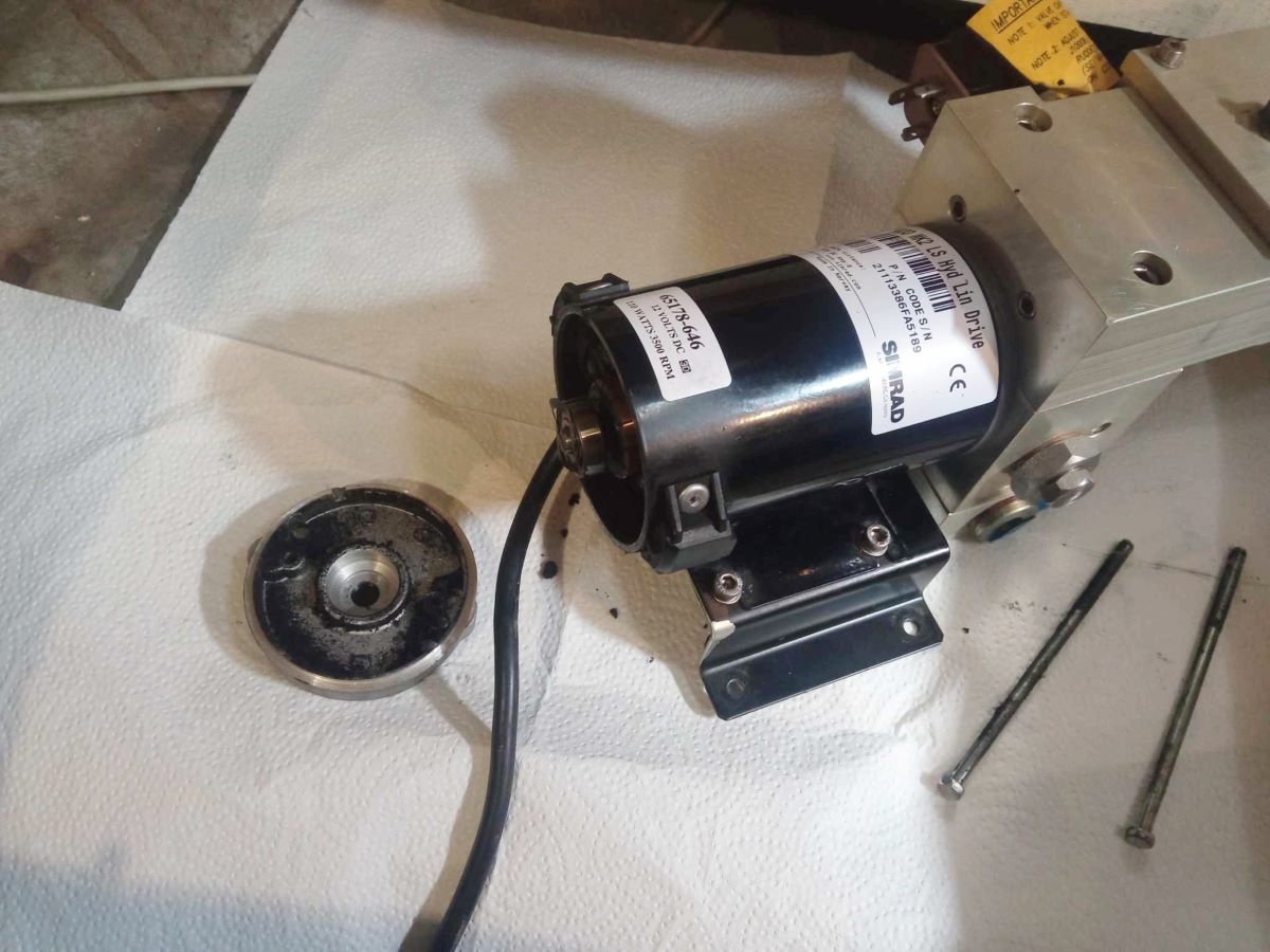
Cleaning the Motor
During removal, we noticed a pile of fine, black dust under where the motor unit had been. Colin guessed that this was carbon dust from the brushes inside the motor. He took the rear bearing cap off of the motor and cleaned up the dust with contact cleaner and paper towel.
Reassembly
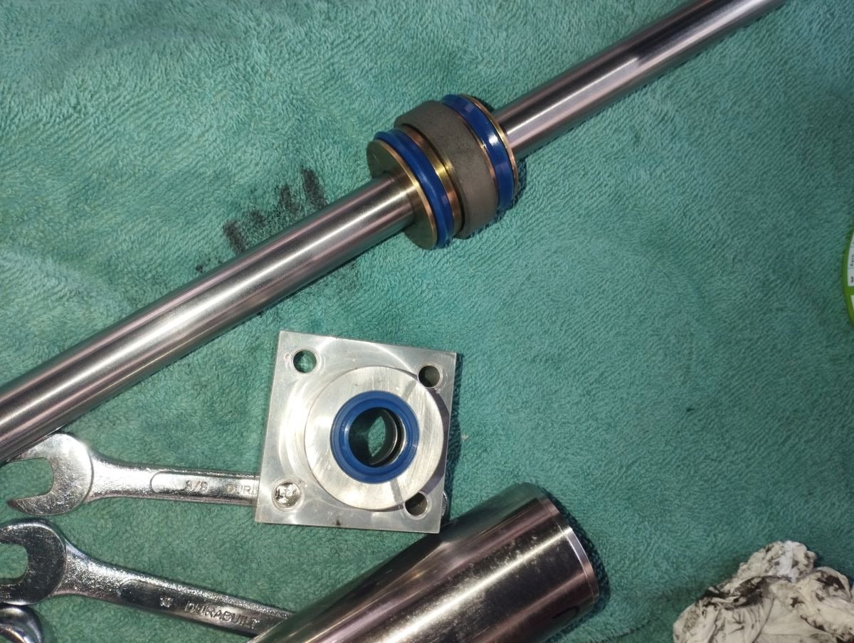
The trickiest part of the process was fitting the piston back inside the cylinder assembly. The new seals were super sticky, even when liberally coated in oil, and the cylinder required some persuasion to slot over them. We noticed that one end of the cylinder has a chamfered end and it was easier to slide this end over the seals than the other.
Two of the seals to be replaced are located on the piston. They are separated by a bearing bush, that we guessed was made of Teflon. We didn’t have a replacement for this and looking at its construction, it seemed extremely vulnerable to damage whilst pushing the piston into the cylinder.
We decided to take the bearing bush out initially whilst we tapped the cylinder over the first bearing. Inevitably, on the first attempt, the cylinder went on too far to then fit the bush in and we had to tap the cylinder back. Of course, it came off completely again. So followed a process of trail and error – tapping the cylinder on hard enough to cover the first seal, then tapping it back enough to fit the bush in. There were several failed attempts before we had success and the cylinder could be tapped on down over the second seal.
Hydraulic Oil
The oil is poured in through an opening in the top of the reservoir. The advice is to fill it to only 3/4 full so that the oil doesn’t burp out over the top as air bubbles escaped. We made a dipstick using a bamboo skewer inserted into the empty reservoir, marking the skewer where the top was. It was then a simple matter of measuring 3/4 of the distance between the skewer end and the first mark and making another mark.

Bleeding the Oil System of Air
The oil needed to flow from the reservoir and fill the hydraulic hoses and the ram. It took a while for the oil to run and fill the spaces it should as we have very little height difference between the reservoir and the ram. Also, we had limited range on the hoses to be able to lift the motor higher to allow gravity to help the oil flow down.
Bleeding was a long, slow process. It was a two person, job, with the first in the cockpit, turning the helm back and forth. The other kept a check on the oil level in the reservoir, topping up as necessary. Burps and bubbles of air were visible through the oil filler hole as the helm turned the quadrant which in turn pushed the ram back and forth, working the oil through the system.
After a while of doing this, we decided to see if the autopilot had any control. We turned the dial on the autopilot controller 10 degrees one way and then the other. As we did this, we could hear the motor and pump trying to respond by pushing oil through the hoses to move the ram. However, there was no movement on the helm, and the autopilot alarm sounded.
So, we repeated turning the helm back and forth, back and forth to keep working the air bubbles out. When we tried using the autopilot control again there was no alarm and the helm moved slightly in response to the dial’s movement. We were getting closer!
We repeated again, turning the helm, then testing with the autopilot control until the helm’s movement was smooth in response.
Testing and Checks
During the bleeding and testing process, we asked ourselves the following questions:
- Did the helm turn in the same direction in which we’d turned the dial?
- Did the rudder move in the correct direction?
One day later we checked again for any oil leaks around the hose ends and ram.
Equipment Needed
We didn’t need any specialist equipment to complete the job and had everything we needed onboard. The tools and resources we advise using are:
- HLD2000 MK2L Instruction manual for parts list and schematic diagrams
- Various spanners size 10mm, 13mm, 14mm, 7/8th
- Shifting spanner
- Ratchet
- Hammer
- Piece of wood to protect the cylinder end whilst hammering
- Small, flat bladed screwdriver, e.g. jeweller’s type
- Needle nosed pliers
- Various trays for storing components
- Stainless steel polish
- Polishing cloth
- Paper towels for mopping up oil
- Jug for pouring the oil
- Funnel with a small enough nozzle to fit in the top of the oil reservoir
- A thin stick to use as a dipstick
- 1.5mm drill bit
Spares and Replacements
Hydraulic Hoses
We hadn’t expected to have to replace the two hydraulic hoses. However, when we inspected them, they were obviously in a bad state of deterioration. The inner core was visible and rusting where the outer protection had cracked away. We had new hoses made which reused the existing end connectors.
The hose specifications are: 3/8″ x 1m long with 3/8″ fittings at each end.

Seals
The autopilot instruction manual has a list of the seals required for the ram as shown in the following table. However, having zero experience with seals and their nomenclature, we needed to research to translate this information to what was available on seal buying websites. We found that the parts list specification translated to the following parts to order:
| Seal Specification in Manual | Description | Seal Name on Seals Website |
| Cleaner 16x24x7,4 | Wiper seal with ID=16mm, OD=24mm, Depth1=4mm, Depth2=7mm | WR16-24-4-7A1-P |
| Oil seal 16x25x5,5 | U ring, rubber with ID=16mm, OD=24mm, Depth1=5.5mm | SU24-16-5.5DI-R |
| Nut ring UM 35-25-5 | U ring, polyurethane with ID=25mm, OD=35mm, Depth1=5mm | SU35-25-5-P |
We chose not to replace the paper gasket seals at each end of the piston. We did have gasket paper available to make our own, but when we inspected the existing gaskets they looked to be in good condition.
We ordered all our seals from FPE Seals in the UK.
Hydraulic Oil
A label on the motor/pump unit specifies the type of hydraulic oil to use as meeting the following standards:
ISO VG 32, DIN 51524 HVLP, AFNOR NFE 48603 HV
We were able to find HM32 oil at a local car parts shop, although they only had 5 litre cans available. We used 0.75 litres.
Costs of Parts
| Item | Cost in euros |
| 3 of each seal ( this included one spare of each) | 54 |
| 2 x 3/8″ hydraulic hoses 1m long | 110 |
| Hydraulic oil 5 litres (we used 0.75 litre) | 30 |
| TOTAL | 194 |
Tips and Advice
Simrad’s UK support team were quick and helpful in response to our questions. You can contact them via the Simrad home page.
The Social Media Bit: Want to Follow Us?
Thank you for reading this far, we really appreciate it. If you’ve enjoyed our site or found it useful, please consider a donation via the DONATE button below. We’re grateful for anything you can spare!
If you’d like to follow us on other social media platforms (Facebook, Instagram and YouTube), you can do so by using these links:
Or use the link below to track our voyage on NoForeignLand.com.
And finally, you can sign up to receive email notifications of new blogs using the subscribe box at the bottom of this page.
Thank you from Nichola & Colin
Very helpful and thanks for taking the time to write this up.
Hi Simon, you’re welcome, glad the article was of use to you